





Water Pump Leak Test Stand for Large Engine Coolant Pumps
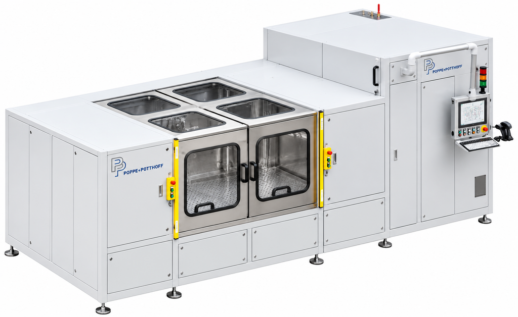
Poppe + Potthoff Maschinenbau built a water pump leak test stand that verifies the shaft seal of every coolant pump for large diesel and gas engines before installation. The pump generates its own test pressure of up to 20 bar, three Coriolis lines record the flow rate, and each result is stored against the pump’s serial number. A crane loads pumps weighing up to 200 kg into a stainless steel test chamber.
Key facts at a glance
| Parameter | Value |
|---|---|
| Test pressure | 0–20 bar (piping rated to 25 bar) |
| Test piece weight | up to 200 kg |
| Flow measurement | 3 pressure lines, each with its own Coriolis meter |
| Pressure ramps | max. 0.5 bar/s |
| Transducer accuracy | class 0.5 % |
| Test medium | Water with 3% anti-corrosion oil emulsion, approx. 1,000 l |
| Noise level | < 75 dB(A) |
| Controls | Siemens S7-300 PLC, industrial touch PC, recipe management |
Why coolant pumps for large engines need an end-of-line leak test
Coolant pumps for large engines run in ships, locomotives, gensets and industrial drives. A leaking shaft seal in these applications means coolant loss, contaminated bearing lubrication and, in the worst case, an engine shutdown far from any workshop.
Replacing a pump after it’s mounted on the engine costs many times more than rejecting it at the end of the production line. That is why every pump has to prove its seal is tight before it leaves pump assembly.
A static pressure test alone does not tell the whole story. A mechanical shaft seal is designed to work while the shaft turns, so its behavior depends on speed, hydraulic load, and a short run-in phase in which the seal faces bed in. A meaningful coolant pump leak test therefore has to reproduce realistic operating conditions.
The second challenge is variety. The pumps differ in size, drive, interfaces, and design, and weigh up to 200 kg. The test stand has to handle all of them without long changeover times.
How the water pump leak test stand works
The stand tests one pump at a time. Each pump family has its own adapter block, which is the only part that changes between families.
The pump is flanged to the adapter block and driven through a flexible coupling at a programmed speed. The pump builds the test pressure itself, so the seal sees real shaft rotation and real hydraulic load. Lube oil reaches the pump bearing through the adapter block.
The system stores speed, run-in time, and hold time per pump type as a recipe. The operator does not set parameters manually; the recipe loads automatically when the pump is identified.
Test sequence in eight steps
- Load. A crane places the pump on a linear slide, which moves it to the drive coupling.
- Identify. A hand scanner reads the pump’s DMC code and loads the stored test program.
- Close. The automatic lift doors close, and the electric interlock is confirmed before the test can start.
- Fill and vent. The test circuit fills with water emulsion and vents automatically.
- Seal run-in. Run the pump at its specific speed for 10 minutes at 5 bar (relative), for example. Any run-in leakage is wiped off.
- Pressure hold. Hold the operating pressure specified on the pump drawing for 5 minutes. Limit pressure ramps to 0.5 bar/s.
- Inspect. After standstill, the operator checks for leakage, visually or with a measuring vessel. A Coriolis meter records the flow rate.
- Drain and save. The circuit is drained. The system stores pressures and flow with the pump’s serial number and can export them via USB or the network.
Separating run-in from the pressure hold matters: initial seepage while the seal faces bed in is not counted as a defect, while leakage at operating pressure is.
Coolant pump leak test design: one self-contained unit
Crane-loaded stainless steel test chamber
The test chamber is stainless steel with a sealed drip tray. Automatic aluminum lift doors with Makrolon windows open fully, allowing the crane to reach the entire chamber. The linear test slide aligns each pump with the motor and coupling.
Three pressure lines with Coriolis flow measurement
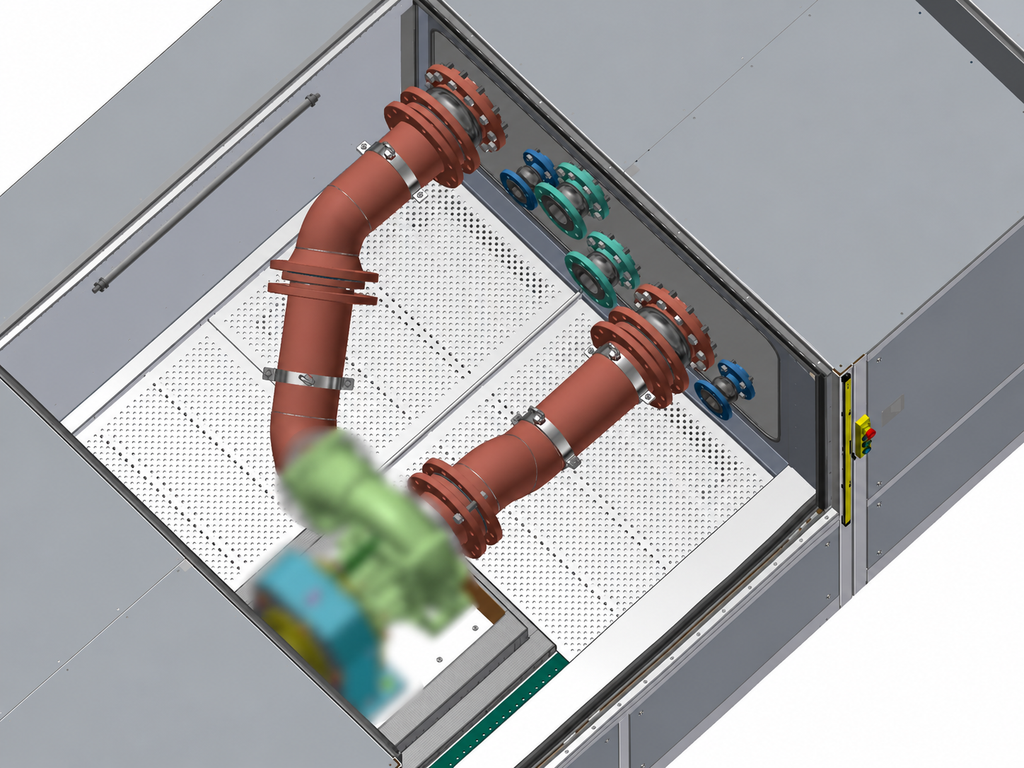
Three independent pressure lines cover different flow ranges; one is active at a time. Each line has its own Coriolis flow meter, so it measures small and large pumps within a suitable range. Pressure transducers are accuracy class 0.5 %.
Media conditioning
A clean and a dirty tank, a band pre-filter, a switchable double filter and bypass filtration keep the test medium clean. The system monitors tank levels and filters, and warnings appear on the operator PC before they affect a test.
Controls, recipes and traceability
A Siemens S7-300 PLC with Profibus runs the stand, operated from an industrial touch PC. The in-house software manages recipes (create, copy, change, delete), shows fault messages in plain text and connects via USB and network. Every test record is linked to the pump’s serial number.
Safety: pressure-free whenever the door is open
The doors of the water pump leak test lock during the test and are monitored by a safety switch. Any fault or emergency stop depressurizes the system, and all connections are pressure-free when the door is open. The electrical design follows EN 60204-1.
Technical data
| Parameter | Value |
|---|---|
| Test type | Leak test, visual assessment with flow measurement |
| Test pressure | 0–20 bar |
| Piping rated to | 25 bar |
| Pressure lines | 3 (one active at a time), each with Coriolis meter |
| Test medium | Water with 3 % anti-corrosion oil emulsion |
| Tank volume | approx. 1,000 l |
| Medium temperature | Room temperature; heating to 90 °C optional |
| Test piece weight | up to 200 kg |
| Test piece connection | Universal fitting via adapter block |
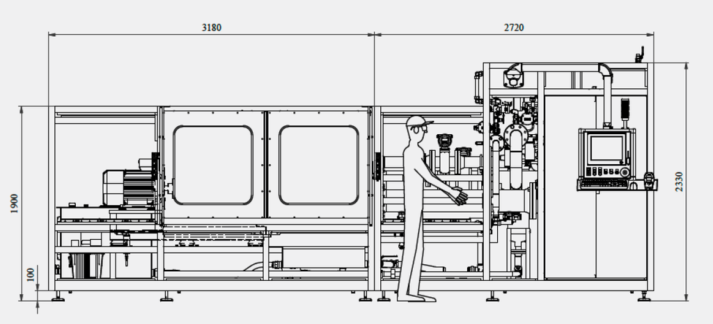
| Dimensions (L × D × H) | approx. 5,900 × [DEPTH] × 2,330 mm |
| Weight | approx. 5,000 kg, empty |
| Finish | RAL 7035 textured; stainless steel chamber |
| Connected load | approx. 15 kW |
| Supply | 230/400 V +6/−10 %, 48–52 Hz; 24 V DC control voltage |
| Compressed air | 6 bar |
| Ambient conditions | 4–40 °C, 75 % RH (annual mean) |
| Water quality | pH 7–8.5, 6–15 °dH, chloride < 100 mg/l |
Leak testing beyond this stand
This stand is one configuration. For pumps that are larger or that need a different test method, we build to specification: our hydrostatic pressure test line for pumps up to 2,000 kg is one example. An overview of methods such as pressure decay, vacuum and gas sniffing is on our leak test stands page, and marine applications are collected under marine and shipbuilding.
Planning a leak test for coolant pumps?
Send us your pump drawing, the operating pressure, and the number of variants. We will propose an adapter concept, a test sequence and a stand layout that fits your production.