





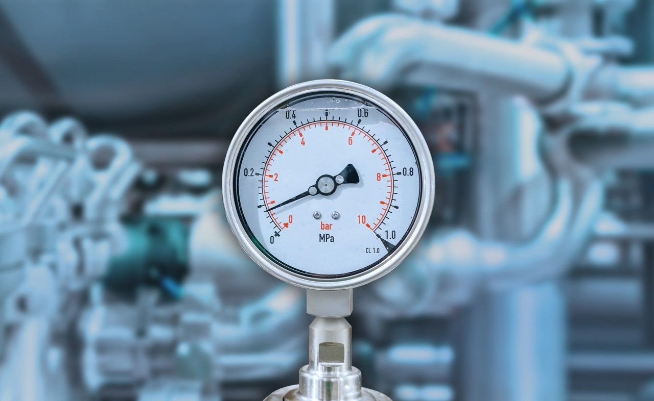
GID Control Modules up to 400 bar. Precise nitrogen pressure control for integration into existing injection molding systems – via EUROMAP 62.
GAS INTERNAL PRESSURE TECHNOLOGY
PRECISELY CONTROLLED
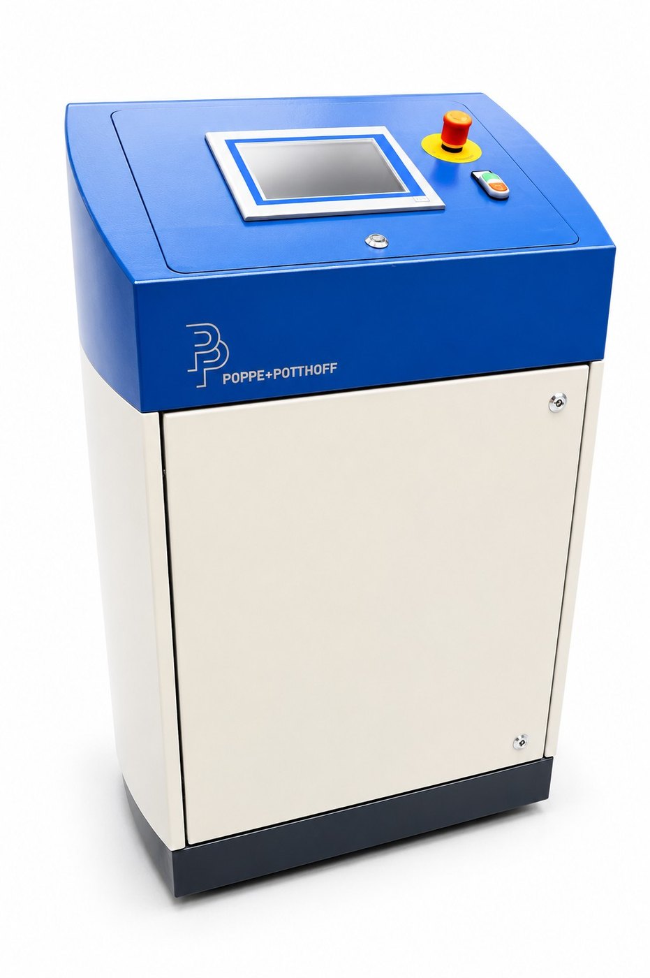
The mobile control module from Poppe + Potthoff Maschinenbau controls the nitrogen pressure in the GID process according to programmable pressure-time profiles – synchronized with your injection molding machine via EUROMAP 62.
The system is installed next to the existing machine and uses your existing nitrogen supply. If the available supply pressure is insufficient, we integrate a P+P booster compressor for pressures up to 400 bar. This allows you to upgrade existing injection molding cells with gas internal pressure technology without replacing the machine.
What is gas-assisted injection molding?Creating defined hollow sections in molded parts
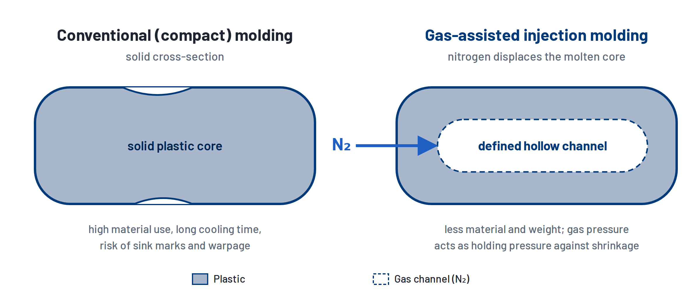
Gas-assisted injection molding – also known as gas injection technology (GIT) or, in German, Gasinnendrucktechnik (GID) – is a special injection molding process. Nitrogen is injected as an inert process gas under pressure into the still-molten plastic. The gas displaces the molten core and forms a defined hollow channel inside the part.
During cooling, the gas pressure partly takes over the holding-pressure function and counteracts shrinkage. For thick-walled parts, handles and components with material accumulations, this reduces material, weight and cooling time and helps to control sink marks.
The challenge: adding gas injection to existing equipment
A typical starting point: a plastics processor wants to add gas-assisted injection molding to an existing injection molding machine – without replacing it. To do this, the nitrogen pressure must be controlled reproducibly, with precise timing and specifically for each part in every cycle.
The solutionP+P gas injection control module PPM/R/400/6
Precise pressure-time control of nitrogen during the injection molding process.
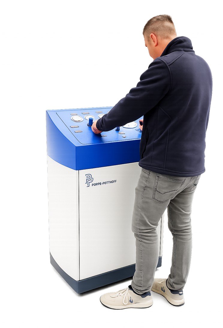
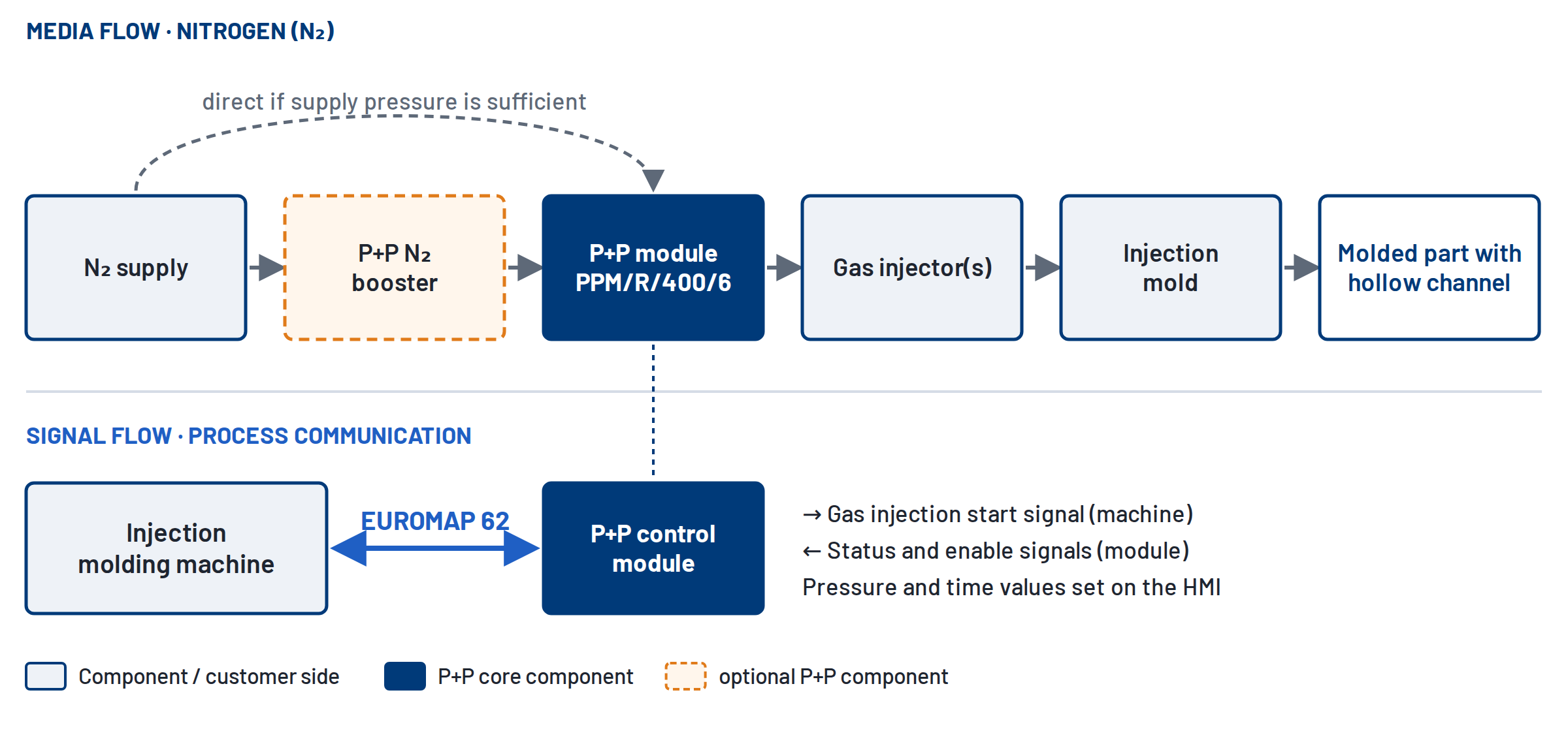
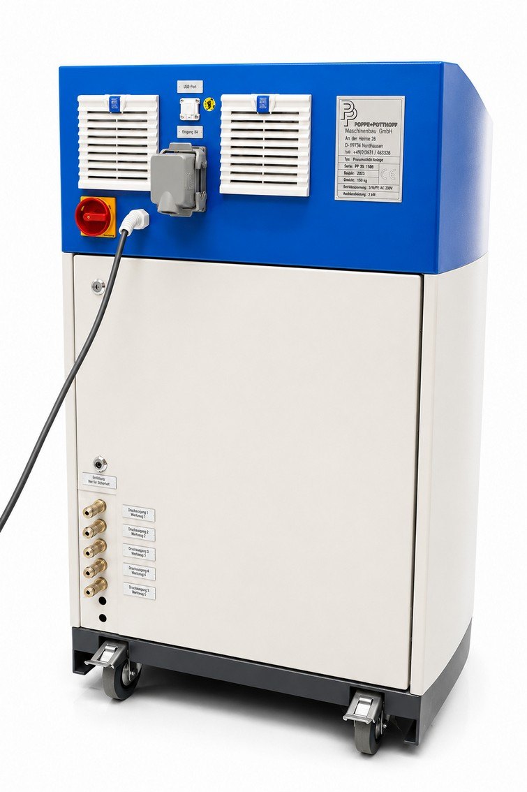
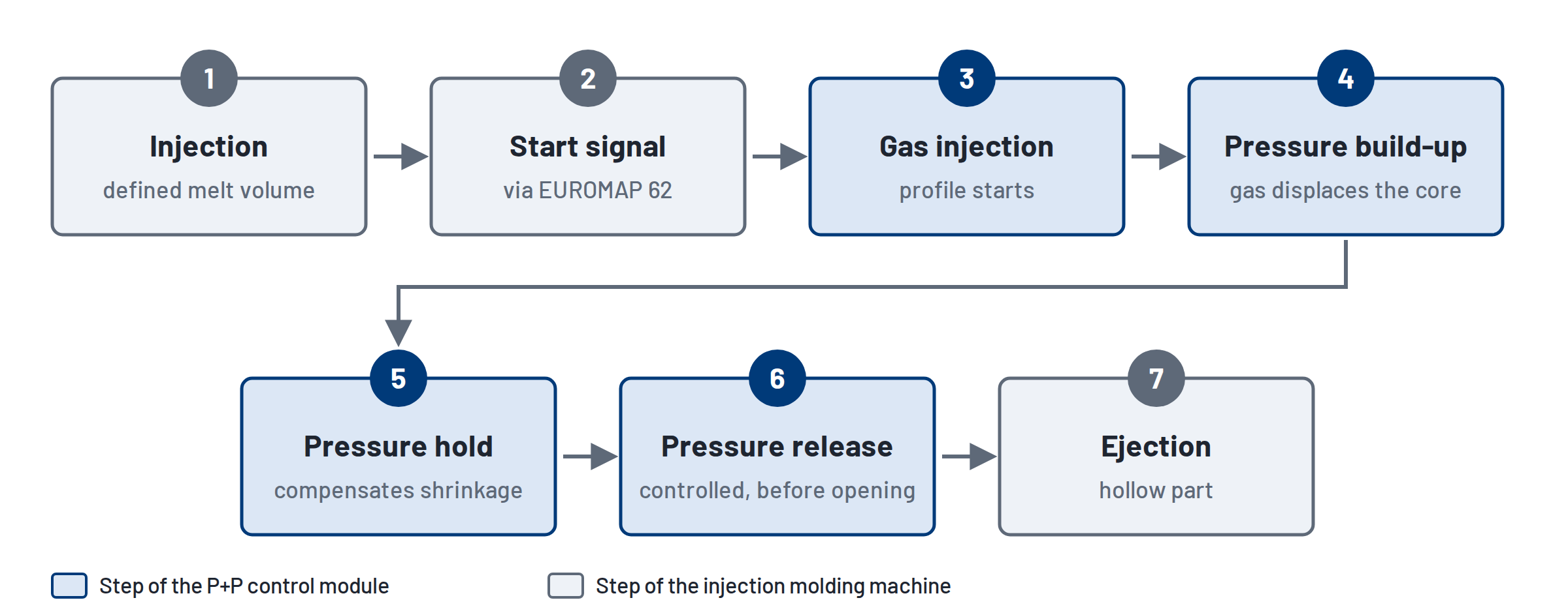
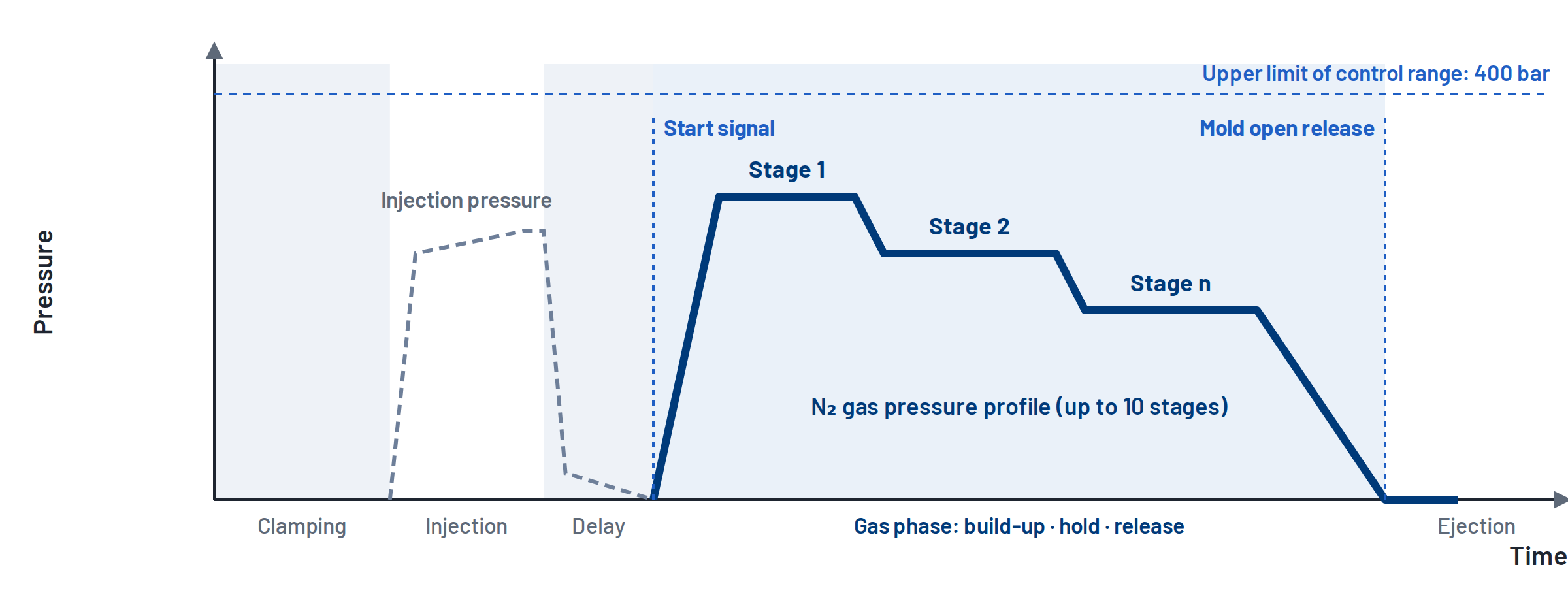
The mobile control module is placed next to the injection molding machine and connected to it via EUROMAP 62. On the machine’s start signal, it builds up the nitrogen pressure in a controlled way, holds it constant and releases it in a controlled way before the mold opens.
The control module thus works as an external, synchronized process unit: it delivers a defined, reproducible pressure-time profile of the process gas – the part itself is formed by the interaction of mold and machine.
Key features
- Mobile control unit – flexible positioning at the production cell
- Six valves, each with its own curve display
- Individually adjustable pressure profiles within a 5–400 bar control range
- 10 pressure stages per profile, 20 storable pressure profiles
- Operating and display unit: B&R industrial PC
- EUROMAP 62 machine interface
- Three 60 µm high-pressure filters
| Your requirement | Poppe + Potthoff answer |
|---|---|
| Keep using the existing injection molding machine | External, mobile control module connected via the standardized EUROMAP 62 interface |
| Reproducible pressure-time profile | Programmable pressure and time values, 10 pressure stages, 5–400 bar control range |
| Multiple control paths | 6 valves with curve display per valve; assignment defined per project |
| Changing parts and molds | 20 storable pressure profiles as part-specific data sets |
| Nitrogen pressure too low | Optional upstream P+P booster unit up to 400 bar |
The strength of the solution is not just the maximum pressure of 400 bar – it is the combination of pressure supply, programmable pressure control, multiple control paths and machine communication.
System layoutMedia flow and process communication
Integration follows two parallel paths: the nitrogen from the supply into the mold, and the communication between injection molding machine and control module.
EUROMAP 62 – the interface to the injection molding machine
EUROMAP 62 is the recommendation for the electrical interface between an injection molding machine and a fluid injection system. It defines connectors and signals in both directions. For gas injection this means: the machine specifies when gas injection starts, the control module runs its stored profile and reports enable signals and status back to the machine.
Integration requirements
- Injection molding machine with EUROMAP 62 interface or corresponding retrofit
- Mold suitable for gas injection, with gas injector(s)
- Safety concept: pressure release before mold opening, integration into the cell
- Suitable N₂ supply plus lines and fittings rated for the pressure range
- Electrical connection according to technical data
Planning gas injection on an existing machine? We review interface, mold and nitrogen supply together with you.
Request a configurationNitrogen supplyuse existing N₂ or boost the pressure
Whether an existing plant supply is suitable depends on more than its static line pressure.
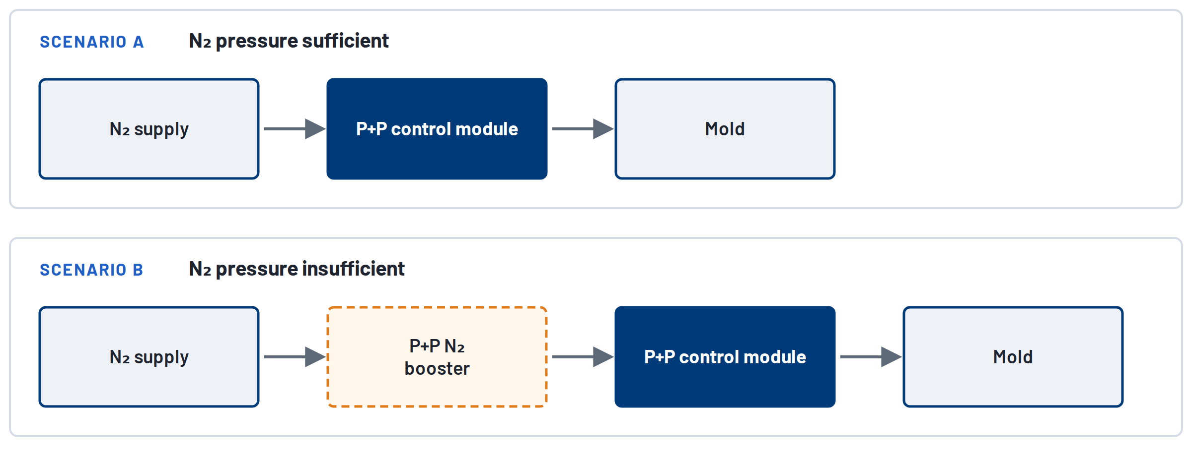
Required process pressure, gas volume and peak flow, purity, pressure stability, line sizing and approved connection components are equally important. This results in two supply scenarios.
Nitrogen pressure sufficient
The existing N₂ supply – cylinder bundle, tank, generator or plant network – is integrated directly into the control module’s supply concept after a technical review. We check pressure, volume, purity and connection components before release.
Nitrogen pressure insufficient
A P+P booster unit is installed upstream. PPM boosters work on the pressure intensification principle: existing compressed air drives the compression, and the available N₂ inlet pressure is used efficiently – up to 400 bar. View the booster units
| Feature | PPM/V/400/120 | PPM/V/400/400 |
|---|---|---|
| Max. operating pressure | 400 bar | 400 bar |
| N₂ cylinder inlet pressure | min. 20–25 bar, max. 300 bar | min. 200 bar, max. 300 bar |
| N₂ tank inlet pressure (tank/generator) | min. 20–25 bar | – |
| Compressed air drive | min. 5 bar, 1/2″ hose connector | min. 5 bar, 1/2″ hose connector |
| Output | approx. 120 Nl/min | approx. 400 Nl/min |
| Outlet pressure regulator | yes | yes |
| Special feature | 5 l buffer volume – cylinder change without production interruption | classic nitrogen boosting application |
Selection and sizing of the booster unit are carried out for each project.
The gas injection cyclefrom injection to hollow part
The machine injects a defined melt volume. At the switchover point it sends the start signal via EUROMAP 62, and the control module runs the stored pressure-time profile: nitrogen is injected, forms the hollow channel and holds the pressure during cooling. Before the mold opens, the pressure is released in a controlled way.
Process variants
Standard process
- Principle
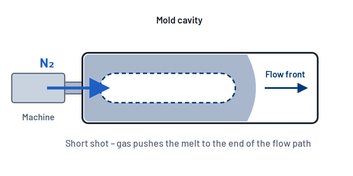
- Cavity partially filled (short shot); the gas pushes the melt to the end of the flow path and takes over the holding pressure.
- Requirement
- Precise dosing of the melt volume, matched switchover point.
- Typical for
- Handles, rod-shaped and thick-walled parts.
Overflow process
- Principle
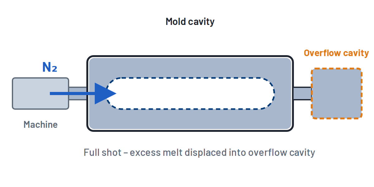
- Cavity completely filled; the gas displaces excess melt into an overflow cavity.
- Requirement
- Mold with overflow cavity and slide, handling of overflow material.
- Typical for
- High surface and dimensional requirements, long gas channels.
Melt push-back process
- Principle
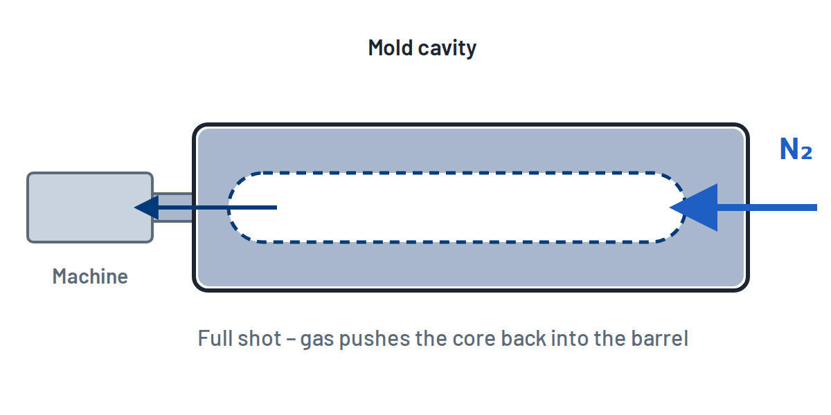
- Cavity completely filled; gas introduced at the end of the flow path pushes the molten core back into the barrel.
- Requirement
- Shut-off gate or machine nozzle, matched mold concept.
- Typical for
- Applications without overflow material.
Multi-channel control: control paths, not simply cavity count
Different flow paths, wall thicknesses and injector positions may require different pressure levels, start times or hold times. Several individually configurable control paths give room for targeted process control.
Technical dataGas injection control module PPM/R/400/6
| General | |
|---|---|
| Type | PPM/R/400/6 |
| Design | mobile control unit |
| Function | Build-up, hold and controlled release of N₂ pressure |
| Pressure & control | |
| Control range | 5–400 bar |
| Number of valves | 6 |
| Pressure stages | 10 per profile |
| Pressure profiles | individually adjustable (pressure and time), 20 storable |
| Curve display | 1 curve per valve |
| Control & interface | |
| Operating/display unit | B&R industrial PC |
| Machine interface | EUROMAP 62 |
| Process start | Start signal from the injection molding machine |
| Media & connections | |
| Medium | Nitrogen (N₂) |
| N₂ inlet | 1 × M16 × 1.5 |
| N₂ outlet | 2 × M16 × 1.5 |
| High-pressure filters | 3 × 60 µm |
| Electrical & mechanical | |
| Power supply | 220 V / 50 Hz |
| Weight | approx. 180 kg |
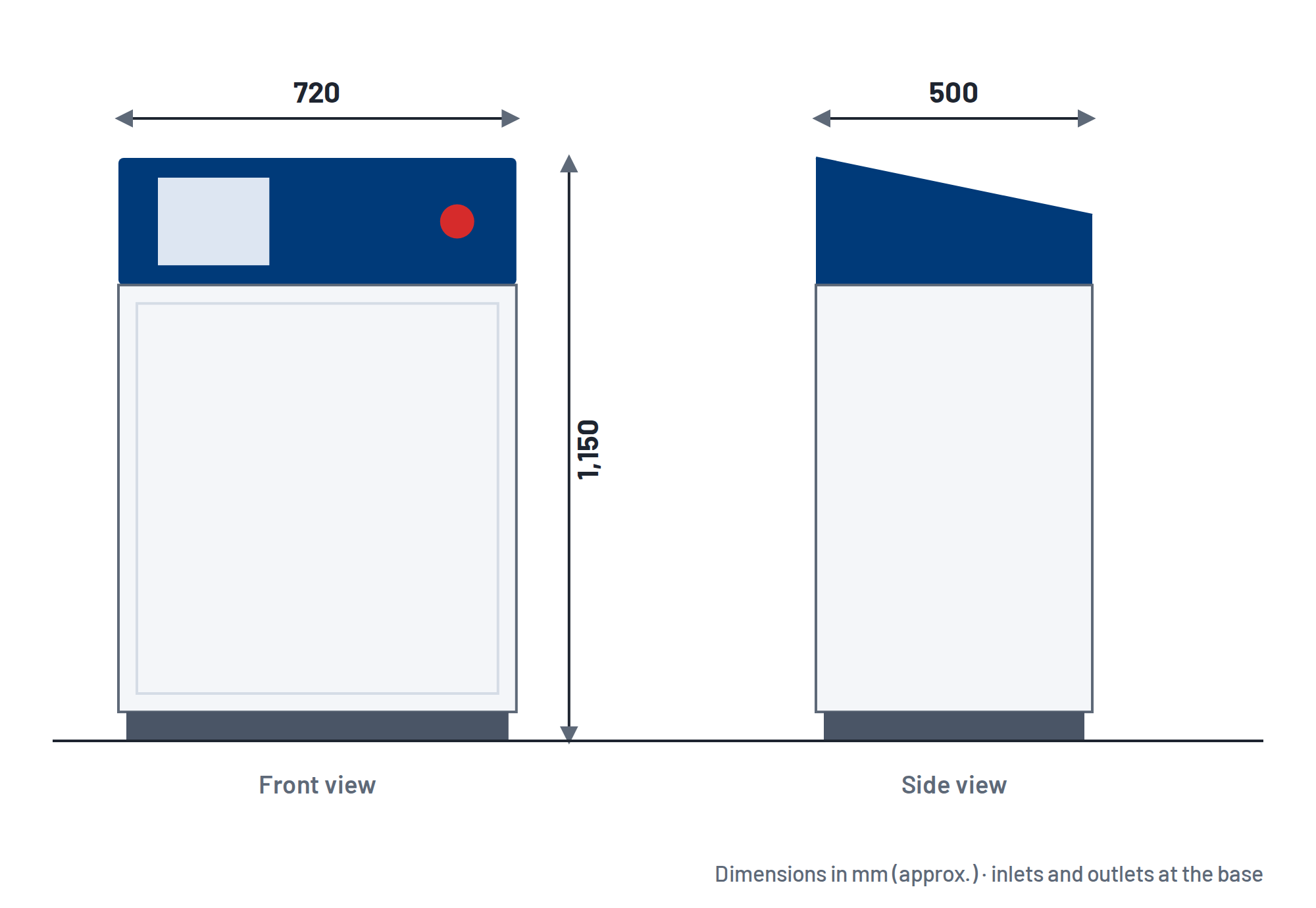
| Dimensions W × D × H | approx. 720 × 500 × 1,150 mm |
| Options | |
| N₂ booster | PPM/V/400/120 or PPM/V/400/400, up to 400 bar |
Technical data subject to project-specific design and technical approval by Poppe + Potthoff Maschinenbau GmbH.
Which configuration fits your mold? Tell us your machine, part and number of gas injectors.
Request a configurationBenefits and applicationswhere gas-assisted injection molding excels
Less material
Hollow channels replace solid cross-sections and reduce material usage in suitable parts.
Lower weight
Lighter part structures – while parts remain strong.
Better surfaces
Gas holding pressure counteracts shrinkage; sink marks and warpage can be reduced.
Thick-walled and long parts
Material accumulations become manageable and cooling times may be shorter. Hollow channels can also serve functional purposes.
Reproducible processes
Programmable pressure-time profiles and 20 storable profiles support stable processes – even when molds change.
Retrofit instead of new machine
Suitable injection molding cells can be upgraded to gas injection via EUROMAP 62 with a mobile control module.
Actual savings depend on geometry, material, mold, gas routing and process parameters. We assess them for each project, on request based on mold trials.
Typical applications
- Automotive: door and roof grab handles, operating levers, technical interior parts
- Household appliances: plastic handles, pot handles
- Furniture: armrests, seat shells, fitting components
- Garden, sports & leisure: garden tools, sporting goods, outdoor furniture
- Logistics & packaging: beverage crates, transport containers, pallets
- Technical moldings: large cross-sections, material accumulations, fluid lines
- Housings & structural parts: large structural components, equipment housings
Where the control module fits best
- Plastics processors introducing or expanding gas injection on existing machines
- Production with frequently changing molds and parts
- Mold making and mold trials on different machines
- Molds with several injectors or zones requiring different pressure profiles
- Sites with an existing N₂ supply that lacks sufficient pressure
Application scenario: retrofitexisting injection molding machine + N₂ infrastructure + P+P control module
Starting point. A plastics processor produces a technical molded part with solid handle and reinforcement sections. Material accumulations cause high part weight and make sink marks hard to control. The existing injection molding machine is to remain in use.
Requirement. Add gas-assisted injection molding without integrating the pressure control into the machine. The existing nitrogen network is to be used; if its inlet pressure is not sufficient, modular pressure boosting is planned.
P+P concept. The PPM/R/400/6 is installed next to the cell as a mobile process module and connected to the machine via EUROMAP 62. At the released process point it receives the start signal and runs the stored pressure-time profile – build-up, hold, release before ejection. If required, a P+P booster up to 400 bar is installed upstream.
Result. A defined internal hollow channel forms in the still-molten plastic. Depending on geometry and process design, the part becomes lighter, uses less material and critical material accumulations become manageable.
| Process | Effect | |
|---|---|---|
| Before | Conventional injection molding with solid sections | High material use, potential sink marks, long cooling |
| After | Gas injection with synchronized N₂ pressure profile | Defined hollow channel, potential gains in weight, material and surface |
Illustrative application scenario, not a reference of a specific customer.
How we work
- Application analysisRecord part, material, mold, injection molding machine and existing N₂ supply.
- ConfigurationDesign control module, control paths, optional boosting and interface for the project.
- Commissioning & mold trialsIntegration into the cell, parameter setting and storage of profiles.
Technical limits and process levers in gas injection
| Effect | Description | Lever |
|---|---|---|
| Fingering | Gas penetrates thinner adjacent areas during cooling | Wall thickness transitions, gas channel geometry, pressure profile |
| Gas blow-through | Gas front breaks through the melt to the surface or flow end | Fill level, delay time, pressure level |
| Unwanted gas penetration | Gas spreads into unintended areas | Injector position, part design, stage profile |
| Varying residual wall thickness | Uneven wall around the gas channel | Melt temperature, pressure build-up, mold temperature control |
| Switchover marks | Marks caused by melt hesitation at the switchover point | Matched transition from injection to gas start |
| Safety | High-pressure nitrogen in the mold | Pressure release before opening, approved components, safety signals |
Frequently asked questionsGas-assisted injection molding and control module
What is gas-assisted injection molding?
Gas-assisted injection molding (also gas injection technology, GIT) is a special injection molding process. Nitrogen is injected under pressure into the still-molten plastic, displaces the molten core and forms a defined hollow channel inside the part. The gas pressure partly takes over the holding-pressure function.
What pressure is required for gas-assisted injection molding?
The required gas pressure depends on part geometry, material, mold and process variant and is determined for each project. The P+P control module PPM/R/400/6 controls nitrogen pressure between 5 and 400 bar with up to 10 pressure stages per profile.
Which gas is used in gas injection molding?
Usually nitrogen (N₂). As an inert gas it does not react with the plastic melt and is available from cylinders, tanks, generators or plant networks.
Can an existing injection molding machine be retrofitted for gas injection?
In principle yes – if the machine has a EUROMAP 62 interface or can be retrofitted with one, a gas-injection-ready mold with gas injectors is available, and nitrogen supply and safety concept are suitable. Poppe + Potthoff reviews these points for each project.
What is EUROMAP 62?
EUROMAP 62 is the recommendation for the electrical interface between an injection molding machine and a fluid injection system. It defines connectors and signals in both directions and enables standardized connection of external gas injection systems.
Can an existing nitrogen network be used?
Yes, if it suits the process window. Besides line pressure, gas volume and peak flow, purity, pressure stability, line sizing and approved connection components all matter. Suitability is technically verified before integration.
When is a nitrogen booster required?
When the available inlet pressure is not sufficient for the required process window. Poppe + Potthoff offers the PPM/V/400/120 (approx. 120 Nl/min, N₂ inlet pressure from approx. 20–25 bar, e.g. from tank or generator) and the PPM/V/400/400 (approx. 400 Nl/min, cylinder inlet pressure 200–300 bar), each up to 400 bar operating pressure.
Which plastic parts are suitable for gas-assisted injection molding?
Mainly thick-walled, long or rod-shaped parts and parts with material accumulations – such as handles for vehicles and household appliances, furniture parts such as armrests, garden and leisure products, beverage crates and large containers, and technical moldings with large cross-sections or fluid lines.
More answers in our frequently asked questions.
Test as a Service
We offer pressure tests in various pressure ranges as a test service. Whether for research and development or serial production, please contact us with your testing requirements.
PRESSURE TEST BENCHES AND APPLICATIONS
PRECISE, REPEATABLE AND RELIABLE
As a specialist in pressure testing technology and state-of-the-art test rigs, Poppe + Potthoff Maschinenbau supports the development and production of particularly resilient components made of various materials – especially for automotive, shipbuilding and mechanical engineering as well as fluid and the medical industry. We offer individually designed test benches such as burst pressure test rigs, pressure cycle test benches, leak test systems, functional test rigs and autofrettage systems.
Pressure change test stand with vacuum testing
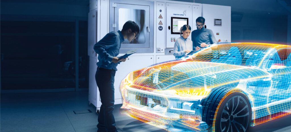
Subject cooling systems of ECUs, PTC heaters, high-voltage coolant auxiliary heaters, ACDC and DCDC converters, and other media-carrying components to pressure tests while controlling the ambient and media temperature of, for example, water-glycol at temperatures from -40 °C to 140 °C.

Function test stand: battery simulation under the influence of temperature
For functional testing of media-carrying components, a temperature-controlled volume flow (e.g. 30l/min) can be generated with the Poppe + Potthoff test benches. In addition, a component from e-mobility can be energized if required.
Leakage test stand
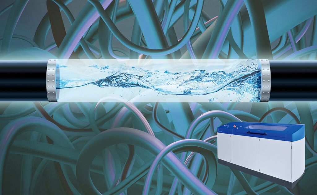
Poppe + Potthoff leak test stands can be used to test various components and assemblies for leaks by means of a pressure drop. Depending on the test requirement, our systems can be designed including vacuum unit and low pressure or high pressure module for optimal leak testing. In addition, Poppe + Potthoff offers e.g. bubble tests in a water bath / underwater tests with air and gas.
Bursting pressure test rig < 200 bar
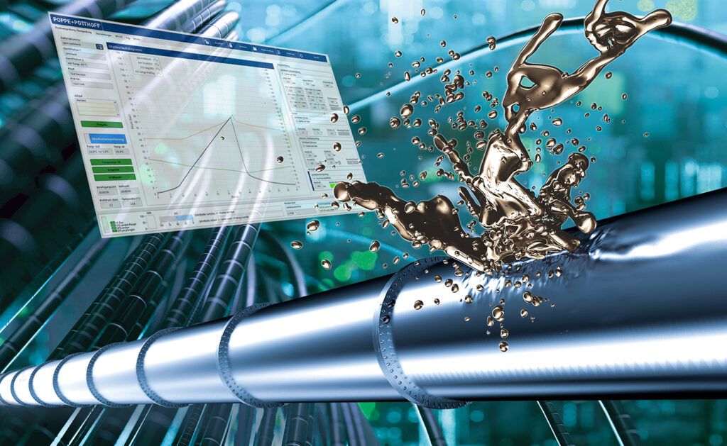
To prove the quality of media-carrying components, hose lines, pipes, pressure vessels and other components are pressurized until they burst.
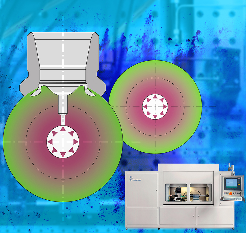
Autofrettage Machine
A flexible and expandable system for performing autofrettage on various components such as common rails and pump heads up to 12,000 bar.
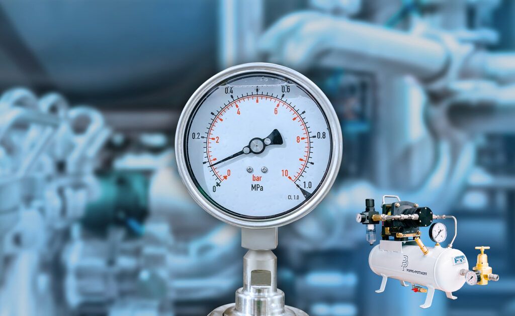
Compressed air booster
Poppe + Potthoff Maschinenbau GmbH supplies compressor units and pressure control systems up to 400 bar. We offer ready-to-connect units to increase the existing pressure for pneumatic and hydraulic applications. This allows the performance of already existing plants to be expanded flexibly and efficiently.
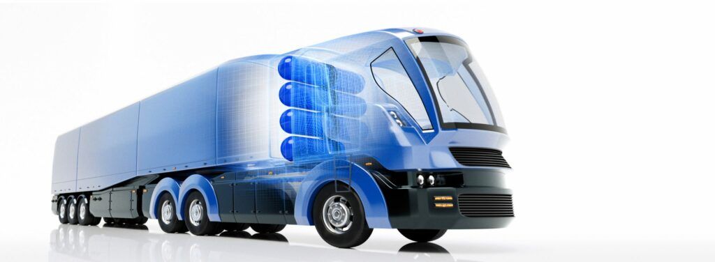
Test bench for H2 components
We offer pressure testing equipment for the development and validation of hydrogen and nitrogen components. The focus is on test benches in the area of pressure cycling, burst pressure testing, and hydrostatic strength testing.
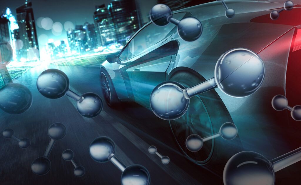
1050 Bar Helium / Nitrogen / Hydrogen
A leak test bench equipped with a pressure module up to 1050 bar, an optional integrated climate chamber and a gas sniffer (e.g. Inficon) to detect leakage on H2 components such as ontank valves, hoses, pipes, fittings, regulators, valves and fuel cell components.
Automotive
Automotive testing involves a wide range of tests. Poppe + Potthoff Maschinenbau supports the industry with state-of-the-art pressure test benches, autofrettage systems and functional test benches.

Aerospace
Test systems from Poppe + Potthoff Maschinenbau put fluid systems and components for aerospace applications to a tough test. In the service life test, they undergo millions of pressure load cycles to simulate the service life of a component.
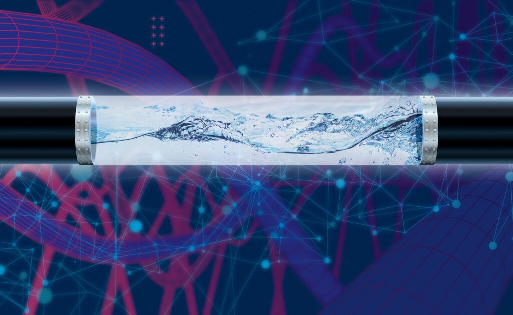
Home Appliances
Household appliance manufacturers are aware of the importance of ensuring that their media-carrying components are leak-proof from day one and that components can withstand a pressure load higher than the operating pressure. Poppe + Potthoff Maschinenbau supports the industry with various pressure testing systems.
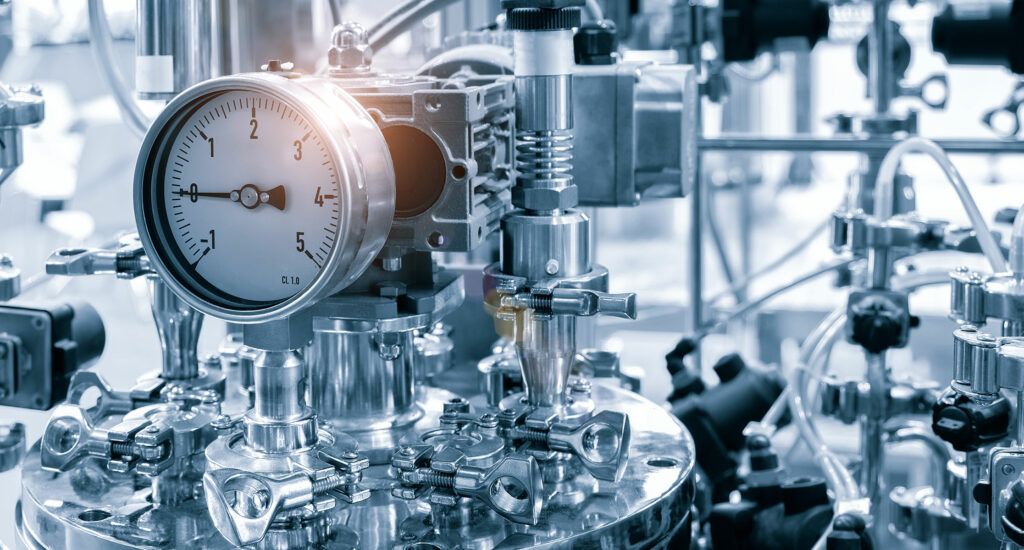
Medical Technology
Test benches for medical technology components from Poppe + Potthoff Maschinenbau put a wide variety of components to the test. Reliable, repeatable and accurate pressure tests and test processes ensure the quality of a component during research and development.

Shipbuilding
Marine engines are composed of components that are exposed to high pressures and require pressure testing of any kind. Cooling systems, pumps and valves of marine engines are exposed to pressure and are tested for their load capacity with pressure test benches from Poppe + Potthoff.

Oil and gas
Various components from the oil and gas industry can be tested on pressure test benches from Poppe + Potthoff. Drill pipes, tubes and (gas) valves are components that are exposed to changing pressure and temperature conditions and require pressure testing to ensure quality and safety.
Contact Us
Our experienced technical sales team will help you implement your project and find a solution tailored to your specifications and requirements. We are represented internationally and can support you and your company worldwide. Our team has completed hundreds of projects many of which involved supporting test facilities with identical equipment. P+P Maschinenbau is your internationally trusted partner.
Expertise, excellent knowledge of the market and affinity for our products guarantee our success.