





Automated Hydrostatic Testing and Autofrettage for Breathing-Air Cylinders
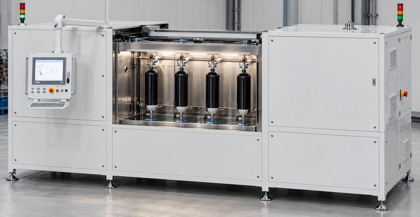
The Poppe + Potthoff four-station test stand fills, leak-tests, autofrettages, and pressure-tests compressed-air and breathing-air cylinders with water up to 700 bar (10,150 psi), then automatically measures their expansion volume. Cylinder manufacturers and requalification facilities get one repeatable, fully documented test sequence for up to four cylinders in parallel.
Why autofrettage and pressure testing matter for breathing-air cylinders
Breathing-air cylinders supply self-contained breathing apparatus (SCBA) for firefighters, rescue teams, and industrial respiratory protection. A cylinder that fails in service fails at the worst possible moment, so every cylinder must prove its strength before filling.
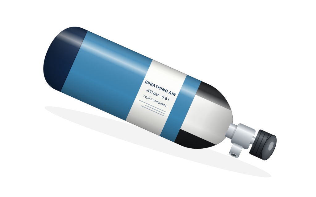
Most SCBA cylinders today are lightweight composite designs. Type 3 cylinders use a seamless aluminum liner wrapped in carbon fiber; Type 4 cylinders use a polymer liner; Type 1 cylinders are all steel. Common working pressures are 300 bar (≈ 4,350 psi) in Europe and 4,500 psi (≈ 310 bar) in North America.
The working pressure is the pressure a cylinder is rated to hold in normal use. Test pressures are set at multiples of that, so the test stand must cover a wide range with precise, programmable control.
Autofrettage is a controlled overpressure step for cylinders with a metal liner. The liner is pressurized beyond its yield point; when the pressure is released, the composite overwrap pushes it back into compression. That pre-stress lowers the liner’s stress during every later filling cycle and improves its fatigue life.
The test sequence step by step
Each station runs the same six-step hydrostatic pressure test. The system stores pressures, ramp rates, and hold times as recipes, so it always tests one cylinder type the same way. It also weighs the part and records the volumetric expansion.
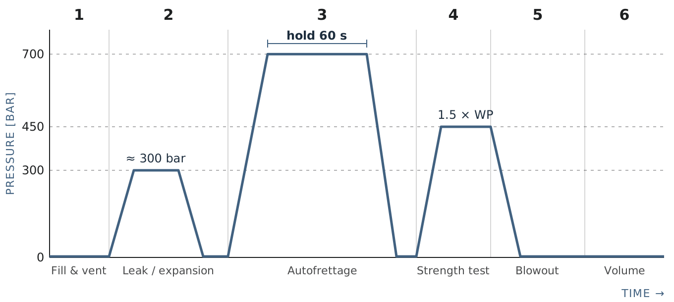
1. Filling and venting
Water enters at the bottom of the cylinder through a lance in the two-channel adapter, while air escapes through the top channel. The result is air-free filling. Trapped air would compress under load and distort the volume results. (For cylinders with two ports the part would fill from the bottom.)
2. Rough leak and expansion test at about 300 bar (4,350 psi)
The cylinder is pressurized to approximately 300 bar (≈ 4,350 psi). This stage detects gross leaks before the cylinder reaches full pressure. The pressure then returns to 0 bar with a short hold.
3. Autofrettage at up to 700 bar (10,150 psi)
A programmable ramp takes the cylinder up to 700 bar (≈ 10,150 psi). The pressure is held for 60 s, then reduced under control rather than dumped. The cylinder returns to 0 bar with a short hold.
4. Pressure strength test at 1.5 × working pressure
The strength test pressure is 1.5 × working pressure, typically 450 bar (≈ 6,525 psi) for a 300 bar cylinder. The cylinder must hold this pressure before the stand releases it back to 0 bar.
5. Controlled depressurization and blowout
After controlled depressurization, compressed air blows the residual water out through the adapter. The cylinder leaves the station nearly dry, ready for the next process step.
6. Automatic volume measurement
Two precision scales record water displacement. Scale A records the water displaced under pressure (the expansion volume); Scale B records the water that returns after release (the elastic recovery). The results are stored with the test report.
7. Optional Drying Station
You can add a dry-out station for up to 8 DUTs. Ideally, separate this process from the test cycle to improve cycle time and throughput.
Pressure profile of one test cycle
How does the water jacket test measure expansion volume?
Classic hydrostatic testing places the cylinder inside a sealed, water-filled jacket and reads the displaced water from a burette or scale. This test stand measures water displacement directly on two precision scales instead.
Elastic recovery is the part of the expansion that disappears when the pressure is released. A cylinder in good condition expands under pressure and springs back. Comparing Scale A (expansion under pressure) with Scale B (water returned after release) shows how much of the expansion was elastic and how much remained.
Because both readings are taken automatically, they do not depend on an operator reading a burette. Both values are written to the test report with the pressure curve.
Safety and data recording
Each of the four stations is a closed, interlocked test chamber. You can open a chamber only when it is depressurized, and it is designed to contain the specimen safely if a cylinder ruptures.
A hydraulically driven Poppe + Potthoff high-pressure intensifier generates pressure, and a pressure transmitter measures it with an accuracy of ≤ ±0.5% of span. A Siemens S7-1500 PLC controls the sequence.
The LabVIEW operator interface displays live pressure curves, manages test recipes, and automatically generates a test report for each cylinder. UV sterilization keeps the circulating test water clean.
Technical data
| Parameter | Metric | Imperial |
|---|---|---|
| Test stations | 4 independent, enclosed stations; parallel or individual testing | |
| Test medium | Water, UV-sterilized circulation | |
| Test pressure range | 10–700 bar (Optional 1050 bar) | 145–10,150 psi |
| Pressure ramp (programmable) | 2–50 bar/s | 29–725 psi/s |
| Rough leak and expansion test | approx. 300 bar | approx. 4,350 psi |
| Autofrettage | up to 700 bar, 60 s hold | up to 10,150 psi, 60 s hold |
| Pressure strength test | 1.5 × working pressure, typically 450 bar | 1.5 × working pressure, typically 6,525 psi |
| Pressure transmitter accuracy | ≤ ±0.5 % of span | |
| Pressure generation | Poppe + Potthoff high-pressure intensifier, hydraulically driven | |
| Volume measurement | Two precision scales: expansion volume (A) and elastic recovery (B) | |
| Cylinder adapter | Two-channel screw-in adapter M18×1.5 with integrated lance | |
| Controls | Siemens S7-1500 PLC; LabVIEW HMI with live curves, recipe management, automatic test reports | |
| Safety | Closed, interlocked chambers; open only when depressurized; designed to contain specimen rupture | |
Discuss your cylinder test with us
Planning a new test line for breathing-air cylinders, or upgrading a manual hydrostatic test? Tell us your cylinder types, working pressures, and the standard you test to, and we will discuss how to configure the sequence for you.
Frequently asked questions
What is autofrettage?
Autofrettage is a controlled overpressure step that plastically deforms a cylinder’s metal liner. After the pressure is released, the liner remains in compression, reducing in-service stress and improving fatigue life. On this test stand, autofrettage runs at up to 700 bar (10,150 psi) with a 60 s hold.
How is expansion volume measured?
The stand measures water displacement on two precision scales. Scale A records the water displaced while the cylinder is under pressure (expansion volume), and Scale B records the water that returns after release (elastic recovery). The system records both values automatically in the test report.
Can you test multiple cylinders at once?
Yes. The system has four independent, enclosed test stations. You can test cylinders in parallel or individually, each with its own recipe. This could be expanded to 8 or 12 cylinders at a time.
What pressure is used for the strength test?
The pressure strength test runs at 1.5 × working pressure, typically 450 bar (≈ 6,525 psi). The recipe sets the exact pressure for each cylinder type. Which test pressure your applicable standard requires is a point to discuss with us at the start of a project.
Can the test stand perform a water jacket test?
Yes, we can implement it if required. The test stand would then perform the water jacket test by automatically weighing the displaced water on two precision scales rather than reading it from a burette. The applicable test pressures and acceptance limits depend on your standard and approval body. We recommend clarifying this with us early in the project.
Which pressure range does the system cover?
The test pressure range is 10–700 bar (145–10,150 psi), with a programmable ramp of 2–50 bar/s (29–725 psi/s). Pressure is measured with an accuracy of ≤ ±0.5 % of span.