





Hydrostatic Pressure Testing of Pumps
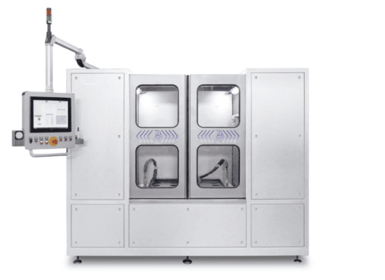
Hydrostatic Pressure Testing of Pumps in Automated Series Production
Testing a single pump under pressure is straightforward. Integrating a repeatable hydrostatic pressure test into a production line handling pumps weighing up to 2,000 kg, filling volumes of up to 120 liters, and numerous product variants is a different challenge altogether.
For a leading European pump manufacturer, Poppe + Potthoff developed several pressure test systems that operate directly within the production process. The systems combine hydrostatic pressure testing, automated material flow, product identification, test data acquisition, and MES connectivity into a single end-of-line testing concept.
The maximum test pressure is 40 bar. But pressure generation alone is not what makes this application demanding. The real challenge is to handle very different pumps safely, fill and vent them reliably, apply the correct test parameters, complete the process within the required production cycle, and assign every result to the correct product.
The pressure test therefore becomes part of both the physical production flow and the digital quality process.
Why is hydrostatic pressure testing used for pumps
Pumps and pressure-retaining pump components must withstand the pressures they will encounter during operation. A hydrostatic pressure holding or strength test provides a controlled method of verifying the integrity of the fully assembled product before it leaves production.
For the test, the pump is filled with water and carefully vented. The pressure is then increased along a defined ramp until the specified test pressure is reached.
Once at the set pressure, the system maintains it for a defined holding period while continuously monitoring the process.
If the pressure development deviates from the permitted range, the system can stop the pressure build-up and depressurize the test part in a controlled manner. The pressure curve and relevant process values are recorded automatically.
This makes it possible to verify pressure resistance and identify significant leakage or unacceptable pressure loss during the test.
Hydrostatic pump testing up to 40 bar
The test systems use water as the pressure test medium. Test pressure can be defined according to the respective product and test program, with a maximum test pressure of 40 bar. The specified pressure holding time is at least 60 seconds. The complete test cycle, including the necessary process steps, is designed for a cycle time of no more than five minutes.
A controlled pressure ramp is particularly important in this type of application. The objective is not simply to reach 40 bar as quickly as possible. Pressure must rise in a predictable and reproducible manner while the control system monitors the response of the test part. An abnormal pressure curve can indicate a problem before the full test pressure is reached. In this situation, the system can interrupt the test and relieve the pressure safely. During the holding phase, the pressure is continuously monitored. Test values and the pressure curve are recorded for subsequent evaluation and documentation. The result is a reproducible pressure test rather than an operator-dependent assessment.
Testing pumps with filling volumes up to 120 liters
One of the main requirements of the project was to test a wide range of pumps on a common platform.
The system is designed for fully assembled dry-rotor pumps, including in-line, twin, and block pump configurations. Depending on the product, its dimensions, connection geometries, internal volumes, and weights vary considerably.
The test spectrum includes:
- Filling volumes from approximately 5 to 120 liters
- Flange sizes from NW 32 to NW 200
- Pump lengths from approximately 400 to 1,200 mm
- Test part weights of up to 2,000 kg
- Product-specific test pressures up to 40 bar
The challenge is therefore much broader than pressure generation.
Every pump must be transported to the testing area, identified, positioned, connected, filled, vented, pressure-tested, drained, and released back into production according to a controlled sequence.
At the same time, the correct test parameters and production data must remain associated with the individual pump.
Example Pressure Curve for a Hydrostatic Pressure Test
The following pressure curve illustrates a hydrostatic pressure holding test on a fully assembled pump with a filling volume of 80 liters. The test pressure is increased in a controlled manner up to 38 bar, held for at least 60 seconds, and then released in a controlled manner.
- Example filling volume
- 80 L
- Test medium
- Water
- Test pressure
- 38 bar
- Pressure holding time
- ≥ 60 s
Note: This graphic shows an example pressure curve within the hydrostatic test process. The described test system is designed for a maximum test pressure of 38 bar and a complete test cycle of no more than five minutes. Pressure ramp, holding time, and other test parameters can be defined according to the specific product.
How the automated pump pressure test works
The pressure test station is integrated directly into the manufacturer’s material and information flow.
Fully assembled pumps arrive at the testing area automatically using an Automated Guided Vehicle (AGV/FTS). At the test station, the operator takes over the pump, positions it in the system, and connects the required test interfaces.
The subsequent process follows a defined sequence.
- Product identification: The pump or production order is identified before testing. This allows the control system to assign the correct test program and product-specific parameters.
- Positioning and connection: The operator positions the pump in the test station and connects the necessary pressure and media interfaces. The flexible adaptation concept allows different pump designs and flange sizes to be processed within the same testing system.
- Filling with water: The pump is filled with the hydrostatic test medium. Because the product range covers internal volumes from approximately 5 to 120 liters, the filling process must accommodate substantial differences between pump variants.
- Controlled venting / air bleeding: Air is removed from the pump before pressure is applied. Reliable venting is an important part of a reproducible hydrostatic test because trapped air can affect both the test process and the pressure system’s behavior.
- Safety enclosure is locked: Once the pump has been connected, filled and vented, the safety enclosure is closed and locked. Pressure buildup is enabled only when all safety-related conditions have been met.
- Controlled pressure build-up: The pressure increases along a defined ramp until the specified test pressure is reached. Depending on the pump and test program, the system can operate at pressures up to 40 bar. The pressure curve is monitored continuously. If the measured pressure falls outside the permitted limits, the pressure build-up can be automatically interrupted.
- Pressure holding phase: Once the required pressure has been reached, the system maintains it for the specified holding period of at least one minute. During this period, the test system monitors the pressure and records the relevant measurement data.
- Automatic evaluation: The test result is evaluated according to the defined process limits. A PASS/FAIL result can be assigned automatically and linked to the respective pump or production order.
- Controlled depressurization: After the holding period, the pressure is reduced in a controlled manner. Access to the test part remains restricted until the system confirms that pressure has been safely relieved.
- Draining and water recovery: The test medium is removed from the pump after the pressure test. Rather than treating the water as a single-use medium, the system filters it and returns it to the storage tank for reuse in subsequent testing cycles. The tested pump can then be released for the next production step.
An end-of-line pressure test integrated into the Smart Factory
In conventional production environments, quality testing can become a separate operation disconnected from the main manufacturing process.
That is not the case here.
The pump pressure test is integrated into both the material flow and the digital production environment.
AGVs transport the pumps between production and testing. Product identification determines which test process has to be performed. Test parameters are assigned according to the respective pump. Measurement values are recorded automatically, and test results are transferred back to the production system.
This means the hydrostatic test is not an isolated quality-control operation at the end of the line.
It is part of the production sequence.
MES integration for automatic test program selection
A central element of the system is its connection to the customer’s Manufacturing Execution System (MES).
Before a test begins, the pump or production order can be identified and matched with the corresponding test program. Relevant order and program information is exchanged with the higher-level production system.
This reduces the need for the operator to select test parameters manually and helps prevent the wrong test program from being applied to a product.
Once testing is complete, the system can return the relevant results to the MES.
Depending on the production environment, this can include:
- Test result
- PASS/FAIL status
- Measured pressure values
- Pressure curve data
- Quality information
- Test and process parameters
- Error messages
- Alarms
- Machine status information
The communication is based on Ethernet/TCP-IP. Depending on the customer’s IT environment, interfaces can include web services, XML via TCP socket, OPC, and database connections.
Complete traceability of every pressure test
For high-volume manufacturing, knowing that the pressure test took place is not enough. The manufacturer must also be able to determine which pump was tested, which program was used, which values were measured, and what the result was.
Product identification and MES integration enable assigning each test cycle to the relevant workpiece or production order.
The recorded pressure curve, process data, and PASS/FAIL assessment can therefore become part of the product’s digital quality record.
This provides the basis for comprehensive traceability in pump production.
If a quality issue has to be investigated later, the manufacturer can refer to the recorded test information rather than relying on a manually documented test result.
Safe pressure testing of pumps weighing up to 2,000 kg
The range of test parts creates significant requirements for handling, ergonomics, and operator safety.
While some pumps are relatively compact, the test system can also accommodate units measuring approximately 1,200 mm in length and weighing up to 2,000 kg.
Pressure testing takes place inside a safety enclosure.
The automatic test sequence cannot begin until the enclosure has been securely closed and locked. During pressure build-up and the pressure holding phase, access to the test part remains restricted.
At the end of the test, pressure is first reduced completely. Only after the system has reached a safe state is access to the pump enabled again.
This safety sequence allows heavy test parts to be integrated into a repeatable production test without compromising the process’s controlled nature.
High product variety on one pump testing system
Producing numerous pump variants makes end-of-line testing more demanding.
A test system dedicated to one fixed product geometry may be relatively simple to configure. A production system handling different pump designs, flange sizes, internal volumes, weights, and test parameters requires significantly more flexibility.
The Poppe + Potthoff concept allows different pump types to be tested within a common system architecture.
Product identification connects the physical test part with its digital test specification. The appropriate parameters are assigned to the product, and the resulting test data is associated with the same production record.
This makes the system particularly well-suited for production environments that require a 100% end-of-line pressure test despite high product variation.
Why the 40 bar pressure level is only part of the engineering challenge
A maximum test pressure of 40 bar does not, by itself, explain the complexity of this application.
The more demanding engineering task is to make the pressure test work reliably in a high-variation production environment.
A pump weighing up to 2,000 kg and containing up to 120 liters of test medium has to move through a repeatable sequence of handling, connection, filling, venting, pressurization, monitoring, depressurization, and draining.
At the same time, the system must know which product is being tested, which parameters apply to it, and where the measurement data has to be stored.
The real capability of the test system, therefore, lies in the interaction between pressure generation, media handling, test-part adaptation, safety engineering, process control, data acquisition, material flow, and production IT.
Technical Data of the Example Pump Pressure Test System
| Parameter | Specification |
|---|---|
| Test method | Hydrostatic pressure holding / strength test |
| Test medium | Water |
| Maximum test pressure | 40 bar |
| Pressure holding time | ≥ 1 min |
| Complete test cycle | ≤ 5 min |
| Test parts | In-line, twin, and block pumps |
| Filling volume | Approx. 5–120 L |
| Flange sizes | NW 32–NW 200 |
| Test part length | Approx. 400–1,200 mm |
| Maximum test part weight | 2,000 kg |
| Pressure control | Controlled pressure build-up with defined pressure ramp |
| Evaluation | PASS/FAIL and detection of unacceptable pressure deviations |
| Material flow | Integration into automated production with AGV/FTS delivery |
| Data acquisition | Automatic recording of test and process data |
| Production integration | MES connectivity |
| Communication | Ethernet/TCP-IP, OPC, and customer-specific interfaces |
| Application | 100% end-of-line testing in series production |
From a Stand-Alone Pressure Test to an Integrated Production Process
Modern hydrostatic pump testing involves considerably more than generating pressure.
In this application, automated material transport, product identification, product-specific test programs, controlled pressure generation, automatic evaluation, measurement data acquisition, and MES communication form one continuous production and quality process.
Poppe + Potthoff combines pressure generation, water management, test-part adaptation, safety technology, process control and production IT in a customer-specific testing solution.
The level of automation can be adapted to the individual production environment – from a manually loaded pressure test station to a highly automated end-of-line test cell with robot or AGV integration.
For pump manufacturers planning a new pressure-testing system, test pressure is only one specification to consider. Product dimensions, internal volume, weight, required cycle time, adaptation, filling and venting strategy, safety concept, test data acquisition, and MES connectivity can be equally important to the performance of the finished system.