




Autofrettage: Process Reliability for Common Rails and High-Pressure Components
How does Autofrettage work? Autofrettage is not simply about reaching a specified pressure. The decisive factor is a stable, repeatable process – from controlled clamping and clean test media to pressure control and complete documentation. This is how we ensure that every component is processed safely and consistently in serial production.
– Philip Claussen // Poppe + Potthoff Maschinenbau GmbH
Components used in high-pressure applications are often exposed to intense, pulsating pressures during operation. For Common Rails, injection lines, injectors, pump heads, and other high-pressure components, fatigue strength is therefore a decisive factor for service life and operational reliability.
Autofrettage is an established process for introducing beneficial residual compressive stresses into highly loaded areas. When properly designed, it improves resistance to cyclic pressure loading and can significantly extend component service life, depending on material, geometry, and pressure cycle load.
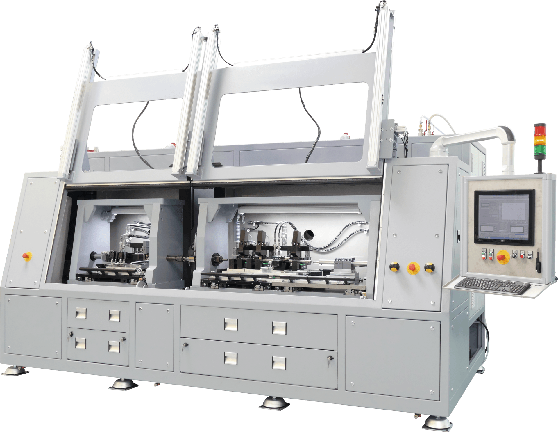
Autofrettage machine with two chambers for the repeatable processing of highly loaded high-pressure components.
What Is Autofrettage?
During autofrettage, a pressure-retaining component is subjected once to a controlled pressure that exceeds its elastic limit in critical internal regions. The inner zone undergoes controlled plastic deformation, while outer areas remain elastic.
Once the pressure is released, the outer zone elastically recovers and creates residual compressive stresses in the plastically deformed inner zone. These stresses counteract the tensile stresses that occur later during operation. As a result, crack initiation and crack growth under repeated pressure loading can be delayed.
In practical terms, autofrettage is not simply a pressure test. It is a defined pre-stressing process designed to improve fatigue strength.
Which Components Are Suitable for Autofrettage?
The machine concept is designed around component geometry, test volume and pressure range. Typical applications include:
- Common Rails and high-pressure fuel rails
- Diesel injection lines and high-pressure injection lines
- Fuel injectors
- High-pressure pump heads and pump housings
- Pipes, fittings and other high-pressure components
- Small pressure sensors and comparable low-volume components
For Common Rail applications, fixtures are often designed for six-cylinder rails. Depending on customer requirements, solutions for eight- or twelve-cylinder rails are also possible. Rails up to approximately one meter in length can typically be integrated; larger lengths up to approximately 1.2 meters can be realized on a project-specific basis.
For typical applications such as Common Rails, pump heads and high-pressure lines, the machine can be designed for pressures up to 12,000 bar. For very small test volumes, such as pressure sensors, pressures of up to 15,000 bar are possible. The actual autofrettage pressure is always defined according to the component and its intended application.
The Autofrettage Process: From Mounted Component to Documented Result
A typical process starts with manually loading the component into a customer-specific fixture. It is then automatically and proportionally clamped. Controlled proportional clamping provides repeatable sealing and is therefore an essential part of a stable process.
After autofrettage, all relevant process data is recorded. This provides transparency for quality assurance, production, and traceability. Depending on customer requirements, an OK component can subsequently receive an identifying mark. Non-conforming components can be manually or automatically separated from the production flow to prevent them from progressing unintentionally to subsequent operations.
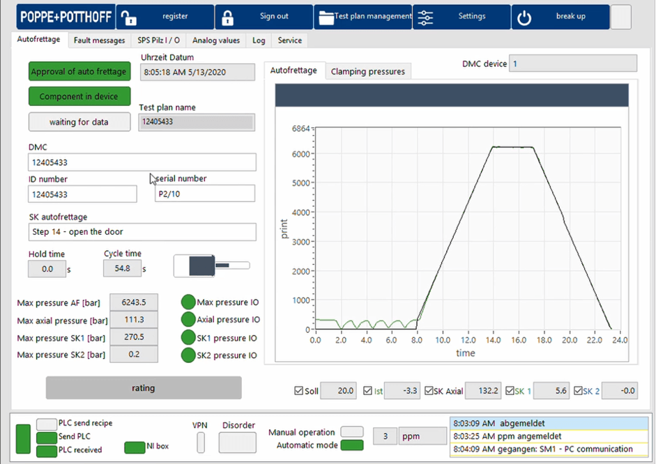
Software of an Autofrettage Machine
Component Cleanliness and Dryness: Essential for a Stable Process
A reliable autofrettage process starts before the component is loaded. The high-viscosity autofrettage oil is part of a closed system that must be kept clean. Residual moisture, cleaning media, or particles from upstream operations must not enter the media circuit uncontrolled.
Particular attention is required after processes such as electrochemical machining, or ECM. Electrolyte residues and moisture may remain after electrochemical machining or deburring and must be reliably removed before autofrettage.
For Common Rails, residual moisture can often be managed through a short blow-off operation before loading. For large pump heads with complex internal passages, however, fluid may remain in cavities or turns. Appropriate drying and cleaning protect the test medium, the seals, and the pressure intensifier.
The cleanliness of the test medium and regular machine maintenance directly affect pressure-intensifier service life. The cleaner the component and test medium, the more stable and economical the overall process becomes..
Increasing Throughput Through Process Parallelization
A typical cycle time is approximately 45 to 70 seconds, depending on the component, test volume, pressure range, and programmed hold time. Smaller rails can often be processed faster, while larger or longer components may require longer hold times.
However, total throughput is determined by more than the autofrettage cycle itself. It depends on how intelligently all process steps are coordinated. While a processed component is cleaned in a separate drip or blow-off station, an operator or robot can already load the next component into the fixture and start the next cycle.
Depending on the application, the machine can also be extended with a second chamber or an additional fixture. Where pressure range and test volume allow, two suitable components can be processed in parallel. This enables the autofrettage system to grow with serial-production requirements, from manual operation to an automated production cell.
Interfaces for Automation and Robotics
Automation does not need to be fully implemented from the start. A machine is often initially operated manually and later expanded with robotics, conveyor technology or automated part separation.
An open interface enables integration into customer-side automation concepts. Loading and unloading, OK marking, NOK separation, as well as drip and blow-off stations, can therefore be adapted to the existing production process.
Safety in Applications up to 15,000 Bar
At very high pressures, operator protection has the highest priority. For this reason, the safety concept is an integral part of every autofrettage machine.
Safety doors are interlocked by the process and are only released when no pressure remains in the system. Machines are designed in accordance with applicable European machinery safety requirements and can be adapted project-specifically for international requirements, including suitable UL design or certification for the US market.
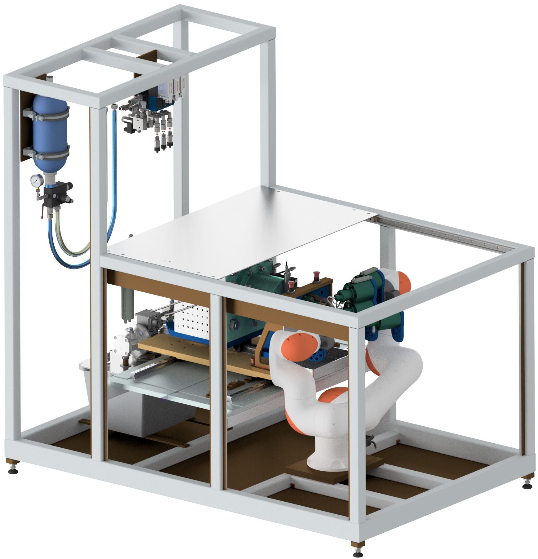
Autofrettagezelle für Einspritzleitungen mit Roboterhandling und Prozessautomatisierung.
Process Know-How for Serial Production
A robust autofrettage solution is not created by the pressure intensifier, fixture and control system alone. What matters is the combination of component knowledge, materials expertise, process engineering and proven implementation.
Our engineering team has worked with autofrettage processes for more than 15 years and has developed numerous fixtures for different high-pressure components. Experience from serial production informs the customer-specific design, the intuitive user interface and the complete process documentation.
Conclusion: Autofrettage as an Integrated Process
Autofrettage combines materials engineering, high-pressure technology, quality assurance and production planning. The greatest benefit is achieved when the entire process is considered: component cleanliness, safe clamping, documented results, marking, part separation and throughput-optimized downstream handling.
We support the design of your autofrettage process – from an individual component to an integrated production solution.
Frequently asked questions about the Autofrettage Process:
Components should be loaded in a clean, particle-free and, wherever possible, dry condition. Residual fluids must be reliably removed, especially after aqueous or electrochemical upstream processes.
Yes. Depending on the process concept, manual or fully automated part separation is possible. OK components can also be marked.
A typical range is approximately 45 to 70 seconds. The actual cycle time depends on the component, test volume, pressure range and programmed hold time.
Yes. Machines can be expanded modularly with robotics, additional fixtures, second chambers, blow-off stations and customer-side interfaces.